Ingiant Medium Frequency Slip-Ring widely applied Video Systems

1. Product Overview
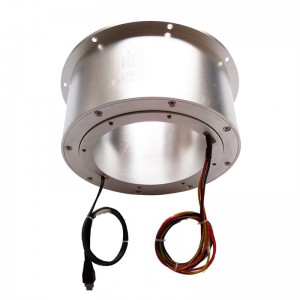
This document describes a non-standard, custom-engineered high-frequency rotary joint designed for continuous transmission of RF signals across rotating interfaces. The device supports three independent 50Ω channels over the 1–5.25GHz frequency range, making it suitable for radar, satellite communication, electronic warfare test benches, antenna positioning systems, and microwave measurement turntables.
Unlike conventional slip rings that transmit power or low-frequency signals, this rotary joint preserves signal integrity – including insertion loss, VSWR, isolation, and phase stability – throughout continuous 360° rotation. It bridges the fundamental engineering challenge of maintaining RF performance between stationary and rotating platforms without cable twisting, bending fatigue, or signal interruption.
2. Complete Parameter Table
| Parameter | Channel 1 | Channel 2 | Channel 3 |
|---|---|---|---|
| Connector Type | SMA-F (50Ω) | SMA-F (50Ω) | SMA-F (50Ω) |
| Frequency Range | 1 – 5.25 GHz | 1 – 5.25 GHz | 1 – 5.25 GHz |
| Average Power (Max.) | 10W | 10W | 10W |
| VSWR (Max.) | 1.5 dB | 1.6 dB | 1.6 dB |
| VSWR Variation (Max.) | 0.1 dB | 0.2 dB | 0.2 dB |
| Insertion Loss (Max.) | 1 dB | 1.2 dB | 1.2 dB |
| Insertion Loss Variation (Max.) | 0.3 dB | 0.15 dB | 0.3 dB |
| Isolation (Min.) | 50 dB | 50 dB | 50 dB |
| Phase Stability (Max.) | ±4° | ±2° | ±2° |
Mechanical & Environmental Parameters
| Parameter | Value |
|---|---|
| Maximum Rotational Speed | 30 RPM |
| Operating Life (Min.) | 5 million revolutions |
| Torque (Max.) | 0.6 N·m @ room temperature |
| Operating Temperature | -40°C ~ +70°C |
| Storage Temperature | -50°C ~ +85°C |
| Relative Humidity (Max.) | 95% |
| IP Rating | IP51 |
| Housing Material | Aluminum alloy |
| Surface Finish | Conductive oxidation |
3. Engineering Interpretation of Key Parameters
3.1 Frequency Range: 1 – 5.25 GHz
This range covers L-band (1–2 GHz), S-band (2–4 GHz), and the lower portion of C-band (4–5.25 GHz). Typical applications include:
- L-band: GPS, BeiDou, IFF (Identification Friend or Foe), air traffic control radar
- S-band: weather radar, shipborne surveillance radar, satellite communication downlinks
- C-band: some satellite TV uplinks, long-range microwave links
Custom versions can extend frequency coverage from DC to 18 GHz, 26.5 GHz, or 40 GHz, or narrow the band to optimize loss and VSWR.
3.2 Average Power: 10W per channel
The 10W continuous wave (CW) rating applies under matched load conditions at room temperature. For pulsed signals with low duty cycles (e.g., radar with 1% duty cycle), peak power may reach several hundred watts. Thermal management becomes critical above 10W, and higher power ratings (50W, 100W) are available through custom design modifications including enhanced heat sinking and dielectric material upgrades.
3.3 VSWR and VSWR Variation
| Channel | VSWR (Max) | Return Loss (approx.) | Reflected Power (approx.) |
|---|---|---|---|
| CH1 | 1.5 dB | 14.0 dB | 4.0% |
| CH2/CH3 | 1.6 dB | 12.7 dB | 5.3% |
A VSWR of 1.5 is considered excellent for a rotary joint over a multi-octave bandwidth. The VSWR variation indicates how impedance matching changes during rotation. Channel 1 achieves ±0.1 dB variation – an extremely tight tolerance indicating exceptional mechanical concentricity and contact stability.
3.4 Insertion Loss and Loss Variation
Insertion loss comprises three components:
- Conductor loss (skin effect in center conductor and outer shield)
- Dielectric loss (PTFE or other microwave substrate)
- Contact loss (rotating interface resistance)
Channel 1: 1 dB max loss with ±0.3 dB variation
Channel 2: 1.2 dB max loss with ±0.15 dB variation
The variation figure is often more important than absolute loss in dynamic systems. For example, a 0.15 dB variation translates to a ±1.7% change in signal amplitude over one full rotation – negligible for most amplitude-based systems such as automatic gain control loops or simple detectors.
3.5 Isolation: ≥50 dB
Isolation is measured between any two channels. At 50 dB minimum, the leakage from Channel 1 to Channel 2 (or vice versa) attenuates a 10W signal to 0.1 mW. This level ensures:
- Transmit-to-receive isolation in full-duplex systems
- Minimal local oscillator bleed-through
- Reduced intermodulation products in multi-carrier environments
3.6 Phase Stability: ±2° to ±4°
Phase stability is arguably the most critical dynamic specification for coherent systems such as:
- Phased array calibration loops
- Interferometric direction finding
- Monopulse tracking radars
- Synthetic aperture radar (SAR)
- Coherent detection receivers
At 5.25 GHz, a ±2° phase change corresponds to a physical path length variation of approximately:
ΔL = (Δφ / 360°) × λ = (2/360) × (299.8 / 5.25) ≈ 0.32 mm
Achieving ±2° stability requires bearing radial runout better than 0.02 mm and precision lapped contact surfaces – a testament to rigorous manufacturing and quality control.
3.7 Mechanical Parameters Explained
Rotational Speed: 30 RPM maximum
Suitable for antenna rotators, test turntables, radar pedestals, and slow-scanning sensors. Higher speeds (up to 300 RPM) are available via custom bearings and dynamic balancing.
Operating Life: 5 million revolutions minimum
At 30 RPM continuous operation, this equals 115 days of non-stop rotation. For typical intermittent use (e.g., 1 hour per day at 10 RPM), the service life exceeds 80 years – far beyond the product’s practical service life.
Torque: ≤0.6 N·m at room temperature
Low torque reduces demands on the drive motor, enables use with small or high-precision positioning stages, and minimizes thermal generation from friction. Torque increases at temperature extremes due to grease viscosity changes.
Temperature Range: -40°C to +70°C (operating)
This meets military-grade (MIL-STD-810) and industrial outdoor equipment requirements. Low-temperature operation is enabled by wide-range lubricants; high-temperature performance requires careful dielectric material selection to prevent deformation.
IP51 Rating
- IP5: Dust-protected (limited ingress of dust, no harmful deposit)
- IP1: Protected against vertically dripping water
This rating suits indoor environments, sheltered outdoor enclosures, and equipment racks. Higher ratings (IP65, IP67) are available for outdoor, shipboard, or desert environments.
Material: Aluminum alloy with conductive oxidation
Aluminum provides lightweight (critical for rotatable assemblies), good thermal conductivity (for heat dissipation from the 10W load), and excellent machinability. Conductive oxidation ensures surface electrical conductivity for RF grounding while providing basic corrosion resistance.
4. Typical Applications
4.1 Ground-Based Radar Systems
Used between the stationary transceiver and rotating antenna array. Three channels support simultaneous transmission, reception, and calibration loop.
4.2 Satellite Communication Antenna Pedestals
Maintains RF link integrity during continuous satellite tracking. Phase stability directly affects modulation error rate (MER) and bit error rate (BER).
4.3 Electronic Warfare (EW) Test Benches
Rotating threat emitter simulators require stable phase and amplitude across multiple channels for angle-of-arrival (AOA) simulation.
4.4 Microwave Medical Equipment
Rotating imaging or therapy heads (e.g., microwave hyperthermia systems) need reliable RF delivery without cable fatigue.
4.5 Industrial Microwave Heating
Rotary joints enable continuous processing of materials in microwave ovens or drying systems.
4.6 Test and Measurement Turntables
Antenna pattern measurement chambers use rotary joints to feed the antenna under test (AUT) while rotating.
5. Non-Standard Customization Capabilities
This product is explicitly designed as a custom-engineered platform. The following parameters can be modified per customer requirements:
| Customization Aspect | Available Options |
|---|---|
| Number of channels | 1 to 8 (or more, with increased diameter) |
| Frequency range | DC–18 GHz, DC–26.5 GHz, DC–40 GHz, or custom bands |
| Connector type | N-type, TNC, BNC, 2.92mm (K), 2.4mm, SMP, SSMA |
| Power rating | 50W, 100W, 200W (with thermal design) |
| Rotational speed | Up to 300 RPM (precision bearings) |
| Environmental protection | IP65, IP67, salt fog resistance, fungal resistance |
| Housing material | Stainless steel, brass, copper alloy |
| Surface finish | Nickel plating, silver plating, gold plating |
| Mounting flange | Custom bolt patterns, pilot diameters, anti-rotation features |
| Phase tracking | Matched phase vs. rotation across multiple units |
6. Quality Assurance & Rigorous Testing
Every rotary joint undergoes a multi-stage qualification process before shipment:
6.1 RF Performance Testing (100% of units)
- VSWR and insertion loss measured across full frequency range (1–5.25 GHz) at 101 points
- Isolation measured between all channel pairs
- All tests performed at static and dynamic (rotating at 30 RPM) conditions
6.2 Phase Stability Measurement
- Phase variation recorded over 10 continuous rotations
- Data logged at 1° increments (3600 points per channel)
6.3 Mechanical Testing
- Torque measured at -40°C, +25°C, and +70°C
- Runout measured at the rotating interface
- Life cycle sample testing: units randomly selected for 5 million revolution endurance runs
6.4 Environmental Stress Screening (sample basis)
- Thermal cycling: -50°C to +85°C, 10 cycles, 2-hour dwell
- Damp heat: 95% RH at +40°C for 48 hours
- Vibration: 5g RMS, 10–500 Hz, per MIL-STD-810
7. Why Choose This Rotary Joint
- Non-standard flexibility – You are not forced into an off-the-shelf compromise. We adapt to your system, not the reverse.
- Rigorous quality control – Every specification is verified. No statistical “typical” values. Each unit ships with a test report.
- Long operational life – 5 million revolution minimum ensures decades of service in typical rotating applications.
- Phase stability leadership – ±2° across three channels is rare at this price-performance point.
- Technical support – Engineering team provides integration assistance, 3D models, and custom drawing approval.