1 Channel RF Rotary Joint DC-67GHz 1.85mm Low Loss Manufacturer

1. Product Overview
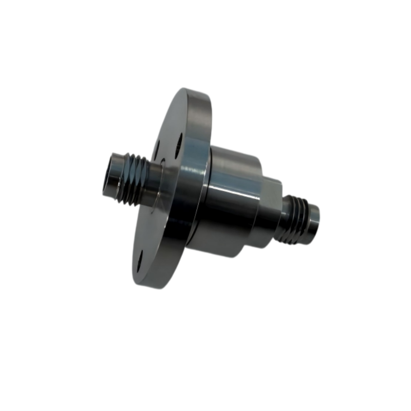
The YZRF-1.85-67G-01 is a single-channel mmWave coaxial RF rotary joint designed for Ka-band SATCOM, 5G/6G mmWave test and electronic warfare platforms. It is mounted at the rotating center of an antenna or turntable to transfer RF signals from the stationary side to the rotating upper structure with 360-degree continuous rotation.
With a 1.85mm (V-type) 50 Ohm interface and 316L stainless steel housing of only Phi 27 x 29.7 mm, it covers DC to 67 GHz in one compact channel – from VHF all the way through Ku, K and Ka bands – and eliminates cable twisting, signal interruption and phase drift under continuous rotation.
2. Key Features
Ultra-wideband in one channel: DC to 67 GHz via a single 1.85mm interface, covering Ku/K/Ka and part of V-band without band swapping.
Low insertion loss: 0.6 dB up to 26.5 GHz, 0.8 dB 26.5-50 GHz, 1.2 dB 50-67 GHz; rotational loss variation held to 0.05-0.15 dB.
Stable VSWR: 1.8 / 2.0 / 2.2 across the three bands, protecting sensitive receivers and power amplifiers.
Long mechanical life: at least 5 million revolutions, 60 RPM peak / 30 RPM average, starting torque under 0.3 N.m.
Rugged 316L housing: -40 to +70 Celsius operating, IP51, qualified to GJB 150 humidity, vibration and shock standards.
Full interface family: SMA, TNC, N Type, 2.92mm, 2.4mm, 1.85mm and 1.0mm connectors from DC to 110 GHz available.
Customization-friendly: flange mounting, cable tails, mixed multi-channel integration and up to 110 GHz variants.
3. Technical Specifications
| Parameter | Specification |
|---|---|
| Model | YZRF-1.85-67G-01 |
| Channel | 1 |
| Interface | 1.85-K (50 Ohm) |
| Frequency Range | DC ~ 67 GHz |
| Insertion Loss | 0.6 dB @ DC~26.5GHz; 0.8 dB @ 26.5~50GHz; 1.2 dB @ 50~67GHz |
| IL Variation | 0.05 / 0.1 / 0.15 dB |
| VSWR | 1.8 / 2.0 / 2.2 |
| VSWR Variation | 0.15 / 0.25 / 0.35 |
| Average Power | 10W / 5W / 3W / 1W |
| Peak Power | 100W / 50W / 30W / 10W |
| Impedance | 50 Ohm |
| Starting Torque | ≤ 0.3 N.m |
| Running Torque | ≤ 0.1 N.m |
| Dimensions | Phi 27 x 29.7 mm |
| Speed | 60 RPM peak / 30 RPM average |
| Service Life | ≥ 5,000,000 revolutions |
| Operating Temperature | -40 ~ +70 Celsius |
| Storage Temperature | -55 ~ +85 Celsius |
| Housing Material | 316L Stainless Steel |
| Protection Class | IP51 |
4. Application In Ka-Band SATCOM & mmWave Test
In a Ka-band ground station or mmWave test turntable, this rotary joint works as the RF bridge between the stationary feed and the rotating antenna.
- • Stationary side (stator): connected to the BUC/LNB or VNA receiver chain.
- • Rotating side (rotor): connected to the antenna feed, tracking mount or positioner.
Transmitted signals include:
- » Wideband RF carrier for Ka-band satcom links
- » mmWave test signal for antenna pattern / TRP measurement
- » Low-level reference / tracking signals with consistent phase
Without a dedicated rotary joint, the coax cable would twist and break after a few rotations, causing link loss or measurement drift.
5. Why 1.85mm DC-67GHz for mmWave Systems
- 1 Standard SMA/N joints roll off sharply above 18 GHz – they simply cannot carry Ka-band.
- 2 The 1.85mm interface keeps VSWR around 2 and IL near 0.8 dB through the whole Ka band.
- 3 Compact Phi 27 body fits gimbal and pedestal mounting envelopes.
- 4 5-million-revolution life supports long unattended tracking and 24/7 test operation.
- 5 Every unit ships with a factory DC-67 GHz swept test report.
For higher-band needs, we recommend the 1.0mm version up to 110 GHz (D-band); for lower-cost fixed Ku-band use, the 2.92mm (40 GHz) or SMA (18 GHz) variants may be sufficient.