


Abstract
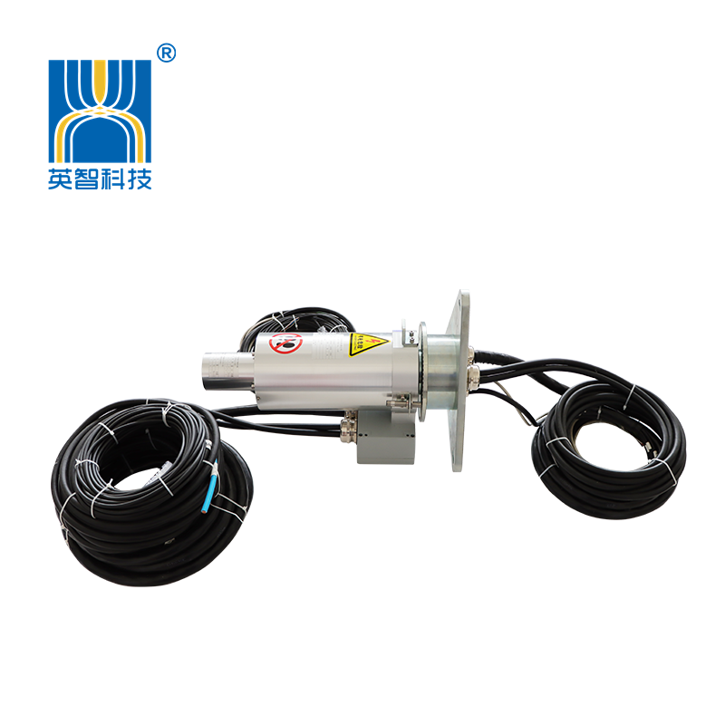
The wind‑power pitch‑controlled slip‑ring serves as a core rotary connecting component of the wind turbine hub rotating system. It undertakes rotary transmission of power supply between the nacelle and hub, safety‑chain circuits, field‑bus communication, as well as rotational speed and position signals. To address the pain points of long lead‑time for spare‑part supply and high operation‑and‑maintenance (O&M) costs of original slip‑rings in existing Goldwind wind farms, Jiujiang In‑giant Technology Co.,Ltd has launched the FHS160‑21‑20212 precision wind‑power slip‑ring. It enables direct compatible replacement for Goldwind‑matched slip‑rings in terms of mechanical interfaces, electrical channels, signal protocols and environmental adaptability, without modifying the overall turbine structure, thus achieving cost reduction, efficiency improvement and independent controllability of equipment. This paper elaborates on this slip‑ring from multiple dimensions including electrical parameters, mechanical structure, integrated sensor design, working‑condition adaptation and key points for on‑site replacement.
1 Working‑Condition Pain Points and Replacement Requirements for Wind‑Power Pitch‑Controlled Slip‑Rings
The pitch‑controlled slip‑rings for Goldwind megawatt‑class units operate inside the hub for long periods, subject to alternating vibration caused by turbine start‑stop cycles, drastic day‑night temperature differences, high‑humidity and dusty environments. During operation, they must transmit high‑power excitation power for pitch‑driving as well as faint signals of CAN bus, safety chain and encoders, imposing stringent requirements on contact reliability, insulation performance and anti‑interference capability.
Original slip‑rings for existing units suffer from the following O&M pain points:
1. Long procurement lead‑time for imported/original‑equipment‑manufacturer (OEM) spare parts, resulting in power‑generation loss during fault‑induced shutdown;
2. High spare‑part prices, keeping high overall costs for overhaul and retrofitting in wind farms;
3. Spare parts for some legacy models are gradually phased out by OEMs, creating risks of no available replacements;
4. Mismatched interfaces or channel definitions of alternative products require modification of nacelle‑ and hub‑side cables during on‑site replacement, increasing retrofitting man‑hours and fault risks.
Accordingly, domestically‑produced alternative slip‑rings must feature fully‑matched mechanical mounting interfaces, one‑to‑one corresponding electrical‑channel definitions, compatible bus signals, and protection‑grade and temperature‑range compliance with turbine design specifications, to realize plug‑and‑play replacement without retrofitting. The Jiujiang In‑giant Technology Co.,Ltd FHS160‑21‑20212 slip‑ring is a compatible replacement product developed for such scenarios.
2 Core Electrical Technical Parameters of FHS160‑21‑20212
1. Insulation and voltage‑withstanding performance: Rated voltage 0‑400 VAC / 1200 VDC; insulation resistance ≥1000 MΩ @500 VDC; dielectric strength: 3500 VAC, 50 Hz, 60 s for power circuits with no breakdown or flashover; 2500 VAC, 50 Hz, 60 s for safety‑chain and CAN‑signal circuits, with leakage current ≤20 mA, complying with industry standards for insulation and voltage‑withstanding of wind‑power slip‑rings.
2. Dynamic resistance variation: ≤10 mΩ. Low and stable contact resistance prevents heating in power circuits and packet loss or bit errors in signal loops.
3. Operating rotational speed: 0‑25 rpm, fully matching the actual operating rotational speed of turbine hubs.
4. Temperature conditions: Operating temperature ‑40 ℃ ~ +55 ℃; storage temperature ‑40 ℃ ~ +70 ℃, covering working conditions of low winter temperatures and high summer hub temperatures for most on‑land wind farms in China.
5. Ingress‑protection rating IP65. The housing adopts aluminium‑alloy and copper‑alloy materials, providing dust‑proof performance and resistance against condensed‑water intrusion inside hubs to adapt to complex hub‑internal environments.
6. Compatibility with 2.0 MW units: The FHS160‑21‑20212 precision wind‑power slip‑ring is mainly applicable to existing Goldwind 2.0 MW direct‑drive permanent‑magnet units (Vensys pitch‑control system), including mainstream on‑land 2 MW models such as GW100/2000 and GW108/2000. Its channels match power, safety‑chain, CAN‑bus, rotational‑speed and angular‑signal interfaces of original slip‑rings for the units; mechanical flanges, zero‑adjustment swing rods and sensor interfaces are fully compatible with original equipment, enabling domestically‑produced replacement without hardware modification of wind turbines.
3 Mechanical Structure and Integrated‑Sensor Design (Key to Goldwind‑Compatible Replacement)
Adaptations are implemented for mechanical outline, flange mounting dimensions, adjustment mechanisms and cable‑outlet forms to enable direct replacement of original Goldwind slip‑rings with no mechanical‑processing‑based retrofitting.
1. Flange and mounting dimensions: Flange positioning holes and M10 mounting threads are consistent with OEM interfaces. An angular‑adjustment swing‑rod mechanism (No. 8 adjustable‑range component) is equipped for slip‑ring zero‑point calibration, following exactly the zero‑setting operating procedure of original units.
2. Integrated all‑in‑one sensor design is a prominent feature of this model:
‑ Integrated Hall‑effect speed sensor SY1230‑H5 for hub rotational‑speed signal acquisition;
‑ Reserved mounting interface for incremental encoder RVP510 (E16066 as alternative option) for hub angular‑position feedback;
‑ Sensors come with 10‑metre 4‑core shielded outgoing cables whose specifications and length match nacelle cabling, reducing on‑site wiring modifications.
3. Clear separation of rotor‑side and stator‑side outgoing‑cable definitions: Drawings explicitly distinguish direct outgoing cables on the rotor side and those on the stator side. Encoders support two mounting configurations: side‑measurement and shaft‑measurement. L1/L2/L3/L4 correspond to different cable lengths for direct plug‑in according to original on‑site cabling.
4. Structural protection details: The enlarged view of View A indicates adjusted sensing distance to guarantee detection clearance of the Hall‑effect sensor. The overall housing sealing structure achieves IP65, blocking dust and condensation from entering ring‑race cavities and lowering the wear rate of brush‑ring‑race pairs.
4 Key Technical Guarantees for Domestically‑Produced Replacement
4.1 Friction‑Pair Material Selection
Copper‑alloy slip‑rings paired with precious‑metal brush‑wires form the friction pair, adopting a multi‑point contact structure to mitigate fluctuation in single‑point contact resistance. Targeting wind‑power operating conditions of low rotational speed, frequent forward‑reverse rotation and intermittent rotation, this configuration suppresses arc erosion and ring‑race oxidation to extend service life.
4.2 Electromagnetic‑Compatibility (EMC) Design
Power cables, CAN‑bus cables and encoder signal cables are routed in separate zones, all fitted with shielding layers with single‑end grounding for shielding layers. Crosstalk from high‑power excitation circuits to weak control signals is minimised, resolving the common “random pitch‑control communication fault” observed at wind farms.
4.3 Maintainability‑Oriented Design
A modular overall structure enables zero‑point calibration on‑site via the swing‑rod zero‑adjustment mechanism. Cable‑connector specifications follow prevailing industry standards. Wind‑farm O&M personnel can complete slip‑ring replacement using existing disassembly‑and‑assembly tools without special training.
5 Key Points for On‑Site Replacement (For Goldwind Units)
| Note: Replacement operations must strictly comply with high‑altitude work safety specifications for wind turbines. Perform unit shutdown, impeller locking, and cut off all power supplies for the hub and nacelle cabinet before commencing work. |
1. Verify channel definitions: Refer to drawings to confirm that definitions of power, safety‑chain and CAN‑bus for the 21 channels correspond one‑to‑one with those of the old slip‑ring. Mark rotor‑side and stator‑side cables to prevent reverse connection.
2. Mechanical positioning and installation: Fasten flanges using original bolts and mount the zero‑adjustment swing rod. Adjust the Hall‑effect‑sensor detection clearance per View A in drawings to ensure normal rotational‑speed‑signal acquisition.
3. Cable connection: Distinguish encoder mounting configurations (side‑measurement / shaft‑measurement), verify L1‑L4 cable lengths, and ground shielded cables in compliance with specifications; avoid forming double‑end‑grounding loops for shielding layers.
4. Zero‑point calibration: Complete slip‑ring zero‑point angular calibration via the swing‑rod mechanism following original‑unit procedures.
5. Static power‑on testing: Perform insulation‑resistance test and continuity test for each circuit. After power‑on, check normal status of CAN‑bus communication, safety‑chain circuits, encoder position and Hall‑effect rotational‑speed feedback.
6. No‑load and loaded trial operation: Manually crank the impeller to rotate at multiple angles. Confirm no communication errors or unintended safety‑chain actions before switching to automatic pitch‑control operation.
6 Conclusion
The Jiujiang In‑giant Technology Co.,Ltd FHS160‑21‑20212 precision wind‑power slip‑ring is developed for domestically‑produced replacement of slip‑rings for existing Goldwind units. Its more than 20 channels fully cover excitation power, safety chain, CAN communication, as well as rotational‑speed‑and‑position sensing functions. With mechanically‑compatible interfaces for original mounting positions, integrated Hall‑effect sensor and incremental‑encoder interfaces, it supports on‑site replacement without retrofitting.
Delivering IP65 protection, wide‑temperature‑range performance down to ‑40 ℃, qualified insulation‑withstanding voltage and stable low dynamic contact resistance, this product addresses O&M challenges including long OEM spare‑part lead‑times, high costs and spare‑part obsolescence. It provides a viable domestically‑produced hardware solution for cost‑efficiency improvement of existing wind farms and independent controllability of rotary wind‑power‑equipment components. In practical projects, the complete channel table of the original unit slip‑ring shall be reviewed prior to replacement to further confirm software‑and‑hardware adaptability and guarantee long‑term safe and stable unit operation.
Post time: Sep-23-2026